This is an old revision of the document!
Table of Contents
Triplanar Mapper
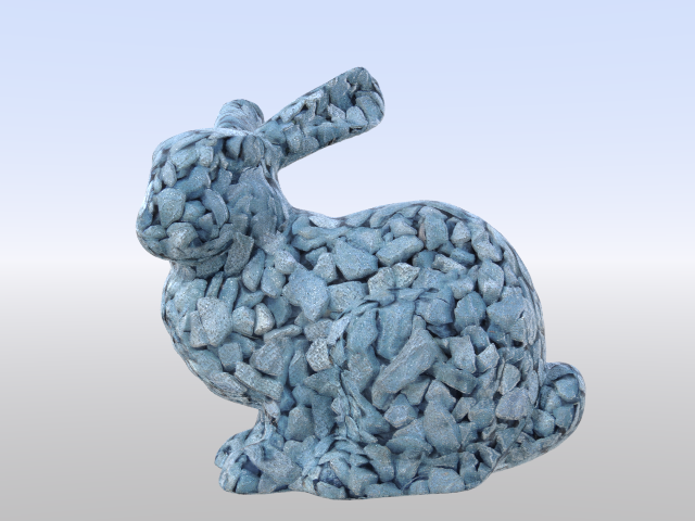
This node maps a single image three times, along each of the major axes (just like cubic mapping) but blends between the three projections depending on the angle of the surface to hide the seams.
This can be used to quickly texture more organic or natural objects without requiring precise UV coordinates.
Controls
Background Colour / Blend Mode / Opacity
These are the standard compositing controls as provided by the native 2D mapping nodes as well.
Triplanar Blend
This controls how hard/soft the blend of the planar projections is as the normals point away from the major axes.
 |  |  |  |
| 0% Blend | 20% Blend | 50% Blend | 100% Blend |
We recommend a value between 5% and 20% for most uses.
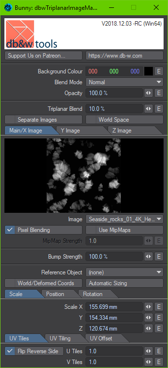
Separate Images
By default, one image is projected on all axes. Enabling this options allows you to pick a separate image for the X,Y and Z axis separately.
World Space
This controls if the blending is computed in local or in world space. Please note, this only affects how the blending is computed, not how the images are projected.
Main / X Image, Y Image, Z Image
The following controls define how the image(s) are projected. The node uses planar mapping for them.
If Separate Images is enabled, the Y Image and Z Image tabs will be enabled as well, otherwise the Main / X Image is used for all axes.
The controls are identical to the ones used by LightWave3D to control the projection of an image, with one exception:
Flip Reverse Side
If this option is enabled, the projected image will be flipped on the U texture coordinate axis on the negative side of the projection. This can be used to make images containing text be readable on the back side of a mesh as well.
Node Connections
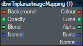
Inputs
Background / Opacity / Blend
These inputs are identical to the ones provided by the native texture mapping nodes for compositing.
Normal
This input overrides the normal used to compute the blending.